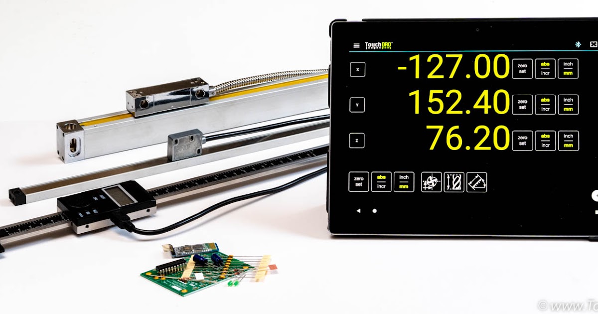
I would like to get a DRO for my mill. Since I live in Canada the selection is poor. To get a Dropro 3 axis glass scale from the U.S.would cost me $1020 for the cheapest one. The exchange rate today was 1.46. Shooting star in Canada sells one but it costs even more. Someone at work showed me.
The remaining gauges have been attached to the DRO. There's now 3 gauges on the lathe and three on the mill. All of the gauge channels are now populated and attached:Poor Man's DRO for Taig Lathe: I have a Taig lathe for some time. Expressburn exe. One of the things which annoys me is that the cross slide turning dial (as well as dials for the other axes) has a lot of backlash which means that it is tedious if not difficult to move the tool to a precise posit. Arduino Based DRO for GRBL CNC Machine: I started this project with a single goal in mind. I wanted a simple, yet effective way to view information about my CNC machine, while standing at the CNC machine, rather than craning my neck in almost contortionist positions, and squinting like a.

Each card has a PIC on it that converts from the gauge serial protocol to I2C. The main ARM processor then interrogates each of the relevant gauge channels over I2C and displays the values.
Each of the gauge channel PCBs is identical, the firmware is almost identical, the only difference is the I2C slave address, which is 0x30 and 0x40 for each pair of PCBs on the same I2C bus. There's three I2C busses.
The main DRO PCB has an ARM processor on a commercial LPExpresso card:
The TFT screen is a touch screen and there's a menu system running on it. The DRO can be set to display the lathe channels or the mill channels. The smaller OLED displays then show the appropriate axis tags. When running in lathe mode the two X axis values can be added together.
The gauges have been attached with 3D printed plastic mounts. I may re-make them in metal if they aren't rigid enough.
The gauges are held in clips that can have screws clamping them from the sides:
I've removed the buttons from the gauges if they were pressed by the clips. The buttons aren't needed and you also don't need to read the displays as the DRO does that.
The batteries aren't needed either as the DRO channels all have a 1V5 power supply. The gauges run from that and are powered all the time the DRO is powered. The power down of the gauge display doesn't stop the serial data stream, either, which is nice.
The mill X gauge is mounted in a similar way:


And the Z gauge:
The lathe bed gauge was one of the more complicated mounting arrangements.
I've started to use the DRO and it certainly makes measuring things much easier. I need to check that the gauges are working correctly by comparing with a dial indicator.
Re: DIY DRO Parallel Guide #sawsetup#diy
Touchdro App

#102728 I wasn't suggesting it would eliminate parallax error, only that the best way to calibrate the DRO is to make it's readout match the measured distance of an off-cut. That said, the extension table he plans on using registers to the Prism on the edge of the slider and thus is square to the slider, and if his distance-stop arm is parallel to that extension table, there should be no parallax error. David Best
|


Each card has a PIC on it that converts from the gauge serial protocol to I2C. The main ARM processor then interrogates each of the relevant gauge channels over I2C and displays the values.
Each of the gauge channel PCBs is identical, the firmware is almost identical, the only difference is the I2C slave address, which is 0x30 and 0x40 for each pair of PCBs on the same I2C bus. There's three I2C busses.
The main DRO PCB has an ARM processor on a commercial LPExpresso card:
The TFT screen is a touch screen and there's a menu system running on it. The DRO can be set to display the lathe channels or the mill channels. The smaller OLED displays then show the appropriate axis tags. When running in lathe mode the two X axis values can be added together.
The gauges have been attached with 3D printed plastic mounts. I may re-make them in metal if they aren't rigid enough.
The gauges are held in clips that can have screws clamping them from the sides:
I've removed the buttons from the gauges if they were pressed by the clips. The buttons aren't needed and you also don't need to read the displays as the DRO does that.
The batteries aren't needed either as the DRO channels all have a 1V5 power supply. The gauges run from that and are powered all the time the DRO is powered. The power down of the gauge display doesn't stop the serial data stream, either, which is nice.
The mill X gauge is mounted in a similar way:
The Y as well:
And the Z gauge:
The lathe bed gauge was one of the more complicated mounting arrangements.
I've started to use the DRO and it certainly makes measuring things much easier. I need to check that the gauges are working correctly by comparing with a dial indicator.
Re: DIY DRO Parallel Guide #sawsetup#diy
Touchdro App
#102728 I wasn't suggesting it would eliminate parallax error, only that the best way to calibrate the DRO is to make it's readout match the measured distance of an off-cut. That said, the extension table he plans on using registers to the Prism on the edge of the slider and thus is square to the slider, and if his distance-stop arm is parallel to that extension table, there should be no parallax error. David Best
|
